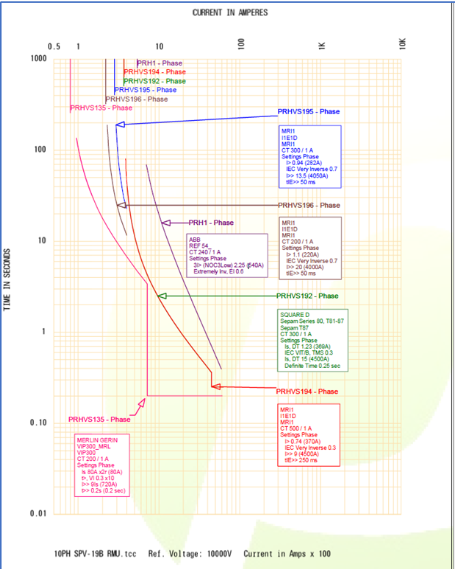
"The biggest challenge with a project like this is ensuring that every element of the electrical network is coordinated with each other to ensure the correct sequence of events occurs if a fault is identified. The procedure of setting overcurrent relays to ensure that the relay nearest to the fault location operates first and all other relays have adequate additional time to prevent them from operating is one of the most challenging aspects of electrical engineering."
Debabrata Manna
Electrical Engineer
Introduction of Solar PV and its effects on incident energy levels
Shortlisted for Engineering Project of the Year at the Pharma Industry Awards 2023, this site was installing solar PV and needed to know how it was going to impact their site and affect arc flash incident levels, as well as the current protection coordination settings.
Client:
Pharmaceutical
Location:
Ireland
Premium Power Role:
Power System Consultants
Project Description
Our strategy was split into four stages, development, analysis, recommendations, and implementation.
Development Stage: We began by developing a model of their electrical system using the software modeling tool SKM. Provided with Single Line Drawings (SLDs), equipment data sheet, breaker, and relay details from the client we set about building an exact replica of their electrical network. Once a model of the current system was built we are able to add the solar panels to see how the network would respond.
Analysis Stage: Armed with our model we began our analysis which involved subjecting the model to a number of simulations and recording the response. We carried out several different operational scenarios and fault testing across multiple locations on-site to determine what was required to maintain smooth operation when the solar PV is engaged. Based on the results of our analysis we were able to calculate the worst-case scenario for arc flash incident energy levels, determining what the risk of an arc flash incident happening is, how severe an incident would be, and what PPE should be worn to prevent injury if an arc flash occurred.
We also conducted short circuit analysis to determine if the equipment on site was capable of withstanding max short circuit faults. Where the calculated max short circuit faults exceeded the device's breaking capacity it cannot be guaranteed that the device will operate as it should in fault conditions. All calculations performed within the created software model are based on the IEC 60909 method C for meshed networks with c factor of 1.1 for MV and 1.05 for LV. All derived values are dependent on the short circuit levels provided at the Point of Common Coupling.
Project Challenges
The client wanted to introduce solar PV to their site (4MW + 3MW) which would work in parallel to their current energy source (electricity from the grid) across their 600 bus network. While this would help the client on their path to net zero emissions, the unpredictable nature of renewables (particularly solar in Ireland) makes it very difficult to manage and control the energy needed to ensure production lines, storage facilities, equipment, etc. continue to work as desired.
We were brought in as Power System Consultants with a scope to determine how the electrical system would operate when the solar panels were introduced, what this meant for employee safety in terms of arc flash levels, and what protection coordination settings needed to be in place to protect equipment from damage.
Project Outcomes
The protection settings response time for the minimum and maximum short circuit fault current was examined and as predicted was deemed not suitable. We proposed protection settings changes that included over current (50/51/LSI) and earth fault (50N/51N/G) settings for the specified protection devices. The proposed protection settings were designed to have the optimal protection operation time and required coordination time interval as well as reduction of Arc Flash energy levels in mind.
We assessed the potential arc flash incident energy levels on site and determined that if the protection settings we recommended were implemented, it would achieve an incident energy of 4.2cal/cm2 and a working distance of 914mm (see table below). This enabled us to offer mitigation solutions including PPE, risk assessments, and equipment labels that would ensure, so far as reasonably practicable, the risk to the safety of workers, such as electricians and others working close to electrical equipment was reduced.
In addition, We were able to verify that the Solar PV will trip only when it is essential to trip in order to protect the equipment and operation at all times.
In the event of a fault on TX-1 PRI:
The fault current seen by PRHVS195 will be 5.7 kA and by PRHVS196 will be 0.4 kA (approx.). This ensures the proposed protection settings will only trip the faulted branch (PV-1) whilst the healthy branch (PV-2) remains operational. (Same philosophy applicable in the event of a fault on TX-2 PRI).
In the event of a fault on Load Centre-13:
The fault current seen by PRHVS195 / PRHVS196 will be 0.4 kA and by PRHVS194/ PRHVS192 will be 0.7 kA (approx.). This ensures the proposed protection settings will only trip the faulted feeder (PRHVS135) whilst the healthy branch (both PV) remains operational.
NEED A SAFE, MORE RELIABLE AND
COST EFFECTIVE ELECTRICAL SYSTEM?
Speak to one of our expert engineers today.
MAKE AN ENQUIRYWHAT WE DO